

Motor Control Panel
Custom motor control panels for single- or dual-motor equipment, built around your motor data, field devices, operator controls, and service needs.
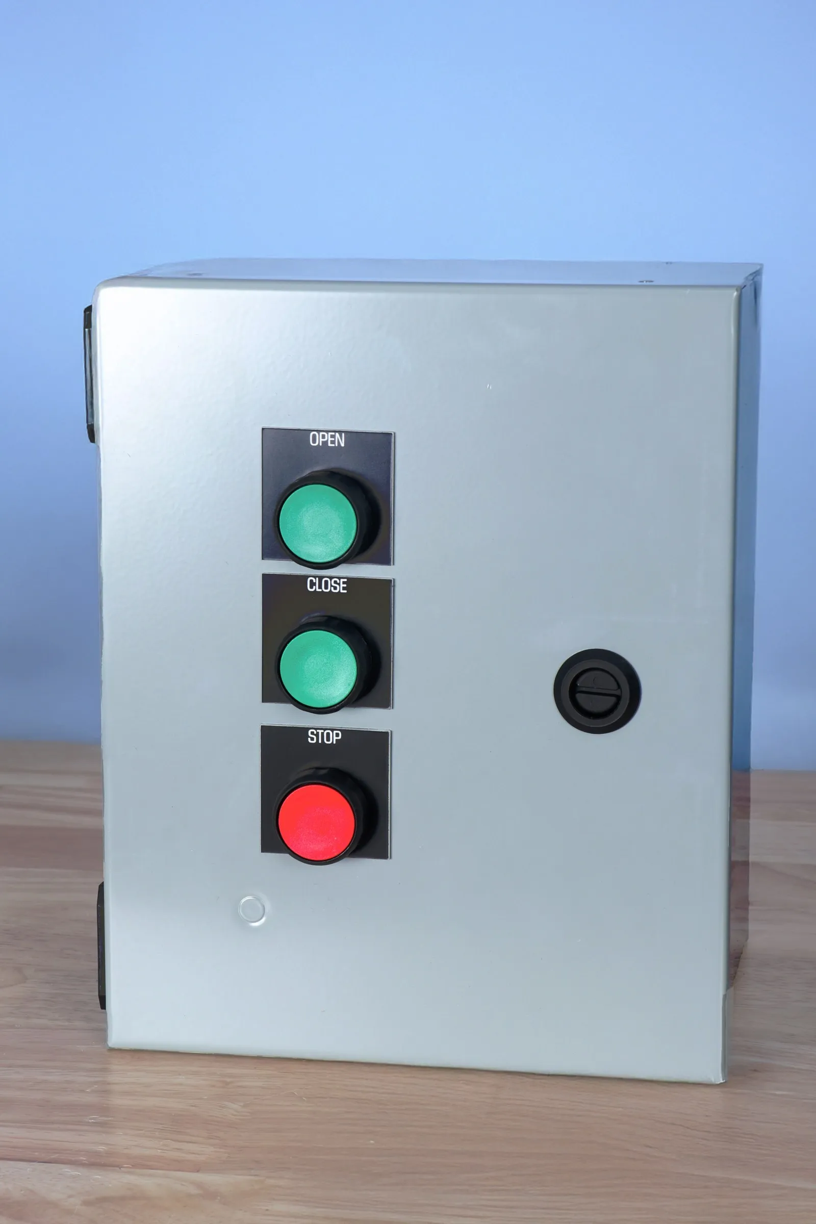
- 1Local buttons
- 2Steel enclosure
Built Around the Motor and the Field Wiring
A useful motor control panel starts with the equipment it will run. We review motor nameplate data, power availability, limit switches, operator stations, interlocks, conduit entry, service access, and labeling needs before recommending a panel layout.
Specifications
| Motor Outputs | Single or dual motor configurations quoted by application |
|---|---|
| Field Inputs | Limit switches, stop circuits, interlocks, and other field devices as specified |
| Enclosure | NEMA 4 steel enclosure option; other enclosure needs reviewed per project |
| Power | Configured around supplied motor nameplate and site power details |
| Documentation | Terminal labels, wiring references, and setup notes quoted with the build |
| Listings | Project-specific inspection or listing requirements must be identified before quoting |
Common Configuration Questions
The fastest quotes come from clear answers to the practical details below.
Motor and Load Data
Voltage, phase, full-load amps, horsepower, actuator type, duty cycle, and any existing control requirements.
Operator Control
Local buttons, remote push button stations, keyed controls, wireless remote, or app-enabled operation when requested.
Field Device Layout
Limit switches, stops, sensors, interlocks, conduit entries, terminal labeling, and service clearances.
What Buyers Should Confirm
Good Fit
- Motorized hatches, doors, actuators, and equipment that need a purpose-built control enclosure.
- Applications where the existing control setup is difficult to service, poorly labeled, or missing the operator controls the site needs.
- Single- or dual-motor equipment that needs clear field termination and straightforward troubleshooting.
Typical Deliverables
- Wired control enclosure configured to the quoted control sequence.
- Labeled terminal blocks and organized field termination points.
- Component layout planned for service access and future inspection.
- Wiring references, setup notes, or other documentation when included in the project scope.
Quote Inputs
- Motor nameplate photos or voltage, phase, horsepower, and full-load amp data.
- Control sequence, operating modes, and stop/interlock requirements.
- Field device list, including limit switches, sensors, remote stations, and existing wiring constraints.
- Enclosure environment, preferred mounting location, and any required inspection, listing, or owner documentation.